Reading Assignments and Exercises
This section is organized as follows:
-
2.1. ISA and Machine Language
2.2. Instruction Representation
2.3. Decision Instructions and Procedure Support
2.4. Number Representations, Data Types and Addressing
2.5. MIPS Programs
2.6. Pointers and Arrays
Information contained herein was compiled from a variety of text- and Web-based sources, is intended as a teaching aid only (to be used in conjunction with the required text, and is not to be used for any commercial purpose. Particular thanks is given to Dr. Enrique Mafla for his permission to use selected illustrations from his course notes in these Web pages.
Reading Assignments and Exercises
2.1. ISA and Machine Language
Reading Assignments and Exercises
The instruction set architecture (ISA) is a protocol that defines how a computing machine appears to a machine language programmer or compiler. The ISA describes the (1) memory model, (2) instruction format, types and modes, and (3) operand registers, types, and data addressing. Instruction types include arithmetic, logical, data transfer, and flow control. Instruction modes include kernel and user instructions.
ISAs are specified in formal definition documents, for example, for the V9 SPARC machine and Java Virtual Machine.
2.1.1. Hierarchical View
As discussed previously, computing languages are translated from source code to assembly language to machine language, as illustrated notionally in Figure 2.1.
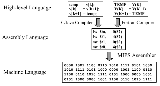
Figure 2.1. Example of computing language translation,
adapted from [Maf01]
The implementation of the ISA in hardware is couched in terms of the fetch-decode-execute cycle illustrated in Figure 2.2. In the fetch step, operands are retrieved from memory. The decode step puts the operands into a format that the ALU can manipulate. The execute cycle performs the selected operation within the ALU. Control facilitates orderly routing of data, including I/O to the ALU's external environment (e.g., peripheral devices such as disk or keyboard).
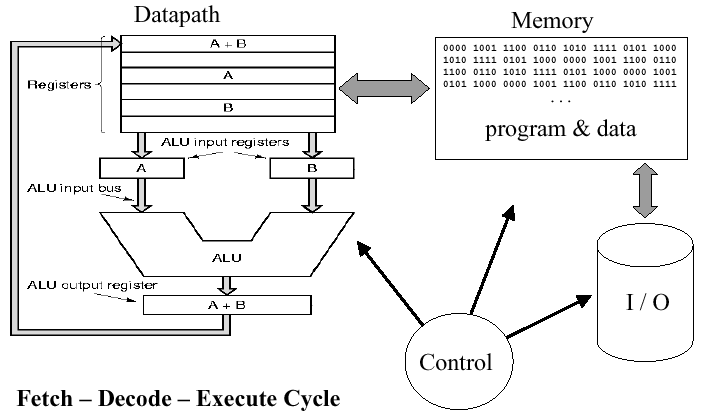
Figure 2.2. Basic ISA cycle, where fetch gets operands from
memory, decode translates the operands into a format the ALU can
accept, and execute performs an ALU operation on the decoded operands -
adapted from [Maf01]
2.1.2. Machine Language
Machne language instructions are of four types: Arithmetic, Logical, Data transfer, and Branches (also called flow control), as follows:
- Arithmetic:
add(addition),sub(subtraction),mult(multiplication),div(division) - Logical:
and,or,srl(shift right logical),ssl(shift left logical) - Data Transfer:
lw(load word),sw(store word),lui(load upper immediate) - Branches:
- Conditional:
beq(branch on equal),bne(branch on not-equal),slt(set on less-than),
- Unconditional:
j(jump),jr(jump register),jal(jump-and-link)
- Conditional:
The MIPS instruction format uses the KISS principle (keep it simple and stupid). As we say more formally:
Design Principle #1: Simplicity favors regularity.
This means that the MIPS instruction format is the same for all instructions. Each instruction begins with an opcode that tells the machine what to do, followed by one to three operand symbols.
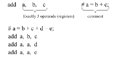
Figure 2.3. MIPS instruction - simple addition example,
adapted from [Maf01]. These instructions are symbolic
examples of what MIPS actually understands.
As an example of the symbolic notation used in Figure 2.3, consider the following equation, expressed in C language format, accompanied by its translation into MIPS assembly language:

Symbolic names make assembly language code more
readable. In the preceding example, note that we have temporary
variables t0 and t1, as well as input/result variables f,
g, h, i, and j. In MIPS, we also have eight temporary
registers labelled $t0 through $t7 and
nine s-registers labelled $s0 through
$s8. The s-registers can be thought of as containing
data that are typically stored in C variables. Thus, in MIPS, operands
cannot be any variable, and there are only thirty-two 32-bit registers
(a memory location that holds 32 bits). This conforms to the
following observation:
Design Principle #2: Smaller is faster.Thus, in proper MIPS code, the preceding example would become:

2.1.3. MIPS Memory
Memory contains instructions and data specific to a
given program. Instructions are fetched automatically by
control, while data is transferred explicitly between the
memory and processor. Figure 2.4 shows an example of memory
operations in MIPS using the lw (load word) and
sw (store word) instructions.
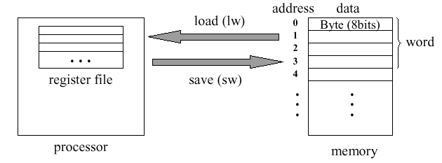
Figure 2.4. Use of lw and sw instructions
to transfer data between memory and processor,
adapted from [Maf01].
Here, data is organized in linear memory as a stream of bits. Each byte is comprised of eight contiguous bits, and each word is comprised of four contiguous bytes.
Data stored in memory is referenced using an
address, which is an identifier that points to a byte in
memory. Addresses in MIPS range from 0 (which points to data in the
part of memory denoted as M[0]) up to 4,294,967,292
(referenced data is written as M[232]). Thus,
all addresses are 32 bits long, so 230 32-bit (four-byte)
words are stored in MIPS memory.
Only load/store instructions can access data in memory. Since each word has length 4 bytes, the addresses referenced by these instructions must be aligned, that is, all 32-bit words start at addresses 0, 4, ..., 4n. Because of differences between computer manufacturers and the way different machines address memory, the MIPS address formats have two types of encoding: big endian and little endian, as shown in Figure 2.5. Here, a decimal (base-10) address of 3,101 is broken down into a hexadecimal (base-16) address of (00 00 0c 1d)16. Big endian stores the big part (00) at the top or beginning of the address, and little endian is the reverse of big endian (stores (1d) at the beginning of the address).

Figure 2.5. Example of big and little endian encoding,
adapted from [Maf01].
There are other interesting things you can do with
memory addressing, such as offsets. For example, suppose you
wanted to add a number in memory location A[2] and put
the result in A[0]. We know that A[2] has
the larger address, and this can be loaded using an offset of 8, as
shown in Figure 2.6. Here, the register $s1 represents
the base address, and the contents of the variable h are
stored in register $s2.
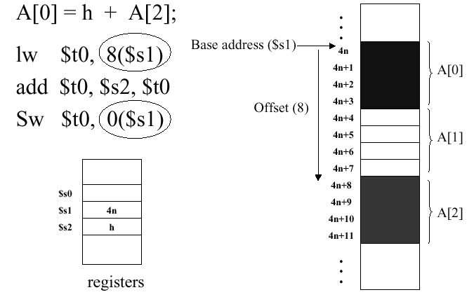
Figure 2.6. Example of memory offsets,
adapted from [Maf01]. The circled operands show how an address offset
is represented in a MIPS instruction.
2.2. Instruction Representation
Reading Assignments and Exercises
Computer instructions are based on three number systems: decimal, binary, and hexadecimal. Salient features of these systems include:
- Binary:
- Digits = {0,1} (Base 2)
- Composition Rule = (dn-1, dn-2, ..., d1, d0)2 => dn-1 · 2n-1 + dn-2 · 2n-2 + ... + d1 · 21 + d0 · 20
- Example = (1010)2 = 1 · 8 + 0 · 4 + 1 · 2 + 0 · 1 = 8 + 2 = 10
- Decimal:
- Digits = {0,1,2,3,4,5,6,7,8,9} (Base 10)
- Composition Rule = (dn-1, dn-2, ..., d1, d0)10 => dn-1 · 10n-1 + dn-2 · 10n-2 + ... + d1 · 101 + d0 · 100
- Example = (2041)10 = 1 · 1000 + 0 · 100 + 4 · 10 + 1 · 1 = 2000 + 40 + 1 = 2,041
- Hexadecimal:
- Digits = {0,1,2,3,4,5,6,7,8,9,a,b,c,d,e,f} (Base 16)
- Composition Rule = (dn-1, dn-2, ..., d1, d0)16 => dn-1 · 16n-1 + dn-2 · 16n-2 + ... + d1 · 161 + d0 · 160
- Example = (c02a)16 = 12 · 163 + 0 · 162 + 2 · 161 + 10 · 1 = 49,152 + 32 + 10 = 49,194
The basic operating concept of modern computers is the stored program, by which programs can be loaded into various partitions (blocks) of memory, then retrieved and loaded into the processor. In the preceding section, we noted that the CPU control does this automatically. In hardware, this is typically accomplished by a device called an instruction sequencer.
2.2.1. Machine Language Instruction Format
In machine language, all instructions have the same length. In MIPS, this design compromise produces instructions that are 32 bits long. The governing principle follows:
Design Principle #3: Good design demands good compromises.
MIPS instructions have three different formats:
- R format - Arithmetic instructions
- I format - Branch, transfer, and immediate instructions
- J format - Jump instructions
These formats are further explained in Figure 2.7. Note that jump instructions merely transfer control (execution) to the specified memory address. As a result, J-format instructions are not very interesting, so we will concentrate the remainder of discussion in this section on R- and I-format instructions.
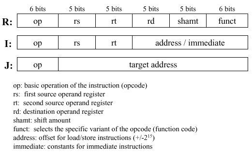
Figure 2.7. MIPS instruction format,
adapted from [Maf01].
Example 1. Consider an example of an R-format instruction
add $t0 $s1 $s2, which means that we add two numbers stored in C registers 1 and 2 ($s1and$s2), then put the result in temporary register 0 ($t0). Here,$t0has the address8, and the C-registers have the addresses17and18. The "$" sign means contents-of. For example$18means contents of register whose address is 18. Also, note that the order of the operands in the machine language instruction (ones and zeros) is different than in the assembly-language version.
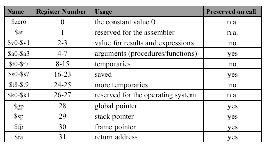
Important Note. MIPS has several register conventions that you should know, which are summarized in the following table. These conventions will be observed as we progress toward more involved MIPS programs.
Table 2.1. MIPS Register Conventions, adapted from [Maf01]
Example 2. A slightly different example of an R-format instruction involves subtraction -
sub $t1 $s1
$s2
, which means that we add two numbers stored in C registers 1 and 2 ($s1and$s2), then put the result in temporary register 1 ($t1). Here,$t1has the address9, and the C-registers have the addresses17and18, as before. Note that thefunctcode for subtraction (34) is different from that for addition (32), and that there is no shifting.
Example 3. Consider an example of an I-format instruction that involves loading a word -
lw $t0
52($s3)
, which means that we load a word into register$t0, which has address 8, by fetching the data from memory location$s3, which has address 19, with an offset of 52.
Example 4. Another example of an I-format instruction involves storing a word -
sw $t0
52($s3)
, which is the opposite of the instruction in Example 3. Note that the opcode for store (43) is different from that for load (35), and that the addresses are kept the same, for simplicity.
We next assemble these concepts together to show how an instruction is translated from a high-level language to assembly language, and thence to machine language.
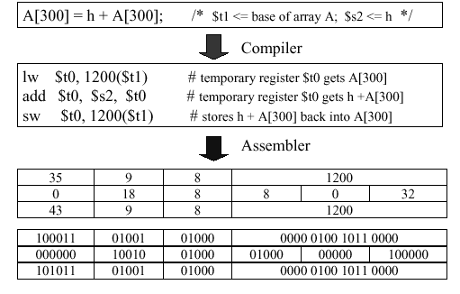
Example 5. Given the high-level statement
A[300] = h + A[300];the following translation sequence holds:
Note that A[300] is stored in memory
with an offset of 1200. This is due to the 32-bit word length (four
bytes) that we discussed in Section 2.1. Since memory is structured
as a linear array of bytes, to obtain the correct byte offset to
maintain word alignment, we need to multiply the memory location in
source code by the word length (e.g., byte offset 1200 = word 300
· 4 bytes/word).
2.2.3. Special Cases
Thus far, we have overviewed the basic add, sub, load, and store instructions. However, MIPS has several special cases of these instructions, which are designed to make programs run much faster. We consider these special cases, as follows.
2.2.3.1. Addition of Constants. By analyzing
large bodies of source code (also called corpi, the plural of
corpus), the developers of MIPS were able to determine that
small constants are used frequently and comprise approximately 50
percent of operands. For example, A = A + 5; and C
= D - 1; respectively are common types of increment or
decrement statements. In general, if an event occurs 50
percent or more of the time, then it is called the common case,
and the following principle applies:
Design Principle #4: Make the common case fast.
As a result of this concept, MIPS puts typical
constants in memory and loads them into special hardwired
registers (e.g., $0).
Example 6. Consider the following add immediate instruction for addition of a register and a constant (I-format):
Here, the contents of C-register
$s7are added to the constant 4 and put into the temporary register$t0. The constant 4 is represented at the right-hand part of the instruction as a two-byte (16-bit) value. The opcode foraddiis 8, which is different from theaddinstruction's opcode (per Example 1, above). As in our previous examples,$t0has the address 7, and it is readily determined that$s7has the address 23.
2.2.3.2. Overflow. Compilers have limited precision (usually 32 bits). If a result of an addition or multiplication is a number that requires a binary representation larger than 32 bits, then we have a problem. We call this situation register overflow, because the number to be loaded into the register is larger (i.e., has more bits) than the register can accomodate.
Some high-level languages (e.g., Ada and certain Fortran compilers) detect overflow, while others (e.g., C) do not. MIPS provides two types of arithmetic instructions:
- add, sub, addi cause overflow; while
- addu, subu, addiu do not cause overflow.
MIPS C compilers produce addu,
subu, and addiu instructions by default,
thereby extending the ANSI standard C language specification.
2.2.3.3. Logical Operations. In MIPS, a logical constant is expressed as a vector of 32 ones and zeroes, not as an integer number. This leads to the practice of bitwise logical operations that operate in parallel upon a vector of Boolean numbers, for example:
(0010 0001 0100) = (0010 0001 0110) and (1010 0011 0101)
In MIPS instructions and and or, the
operands are registers, and the R-format instruction is used (similar
to the add instruction in Example 1, above). In contrast, MIPS
instructions andi and ori have operands that
are immediates, and the I-format instruction is used. An example of
the I-format logical instruction follows.
Example 7. Consider the following
andiinstruction for and-ing a register and a logical constant (a Boolean number):andi $t0, $t0, 0xFFF
This instruction has several interesting characteristics. The first operand is stored in register t0, and is anded with a logical constant specified in hexadecimal as 0xFFF. This representation means fill the word with zeroes until you get to the last three digits, which are f, f, and f. Since F16 = (1111)2, we have the second operand shown above. When the logical and operation is applied bitwise to these operands, the result is shown below the line. Note that the word 0xFFF is called a mask because anding causes the result to be zero (one) in those bit positions where the mask has the value of zero (resp. one).
2.2.3.4. Shift Instructions. In order to move the contents of a register to the left or right efficiently, MIPS has a dedicated shift capability that is controlled by the following shift instructions:
- sll (shift left logical): fills empty bits with zeroes
- srl (shift right logical): fills empty bits with zeroes
- sra (shift right arithmetic): sign extends empty bits
Example 8. Assume that the R-format instruction
srl $t0, $s1, 8is applied as shown below. The shift amount, represented as shamt, is the number of bits to shift the operand$s1to yield the result in$t0.
Since the instruction is R-format, note that the opcode is modified by the funct descriptor (000010) that occupies the last six bits of the instruction. Shift instructions are used for a wide variety of operations, including the pencil-and-paper algorithm for multiplication of binary numbers.
2.2.3.5. Multiplication and Division. We will discuss multiplication and division in MIPS in detail in Section 3.3. For now, consider the following information as useful in the context of the MIPS instruction format.
Multiplication and division of two N-bit numbers produce a result that can be as large as 2N significant digits (i.e., 2N bits). As a result, MIPS uses two registers, called hi and lo, to store the upper and lower parts of the product (for multiplication) as well as the remainder and quotient (for division).
Example 9. Assume that
mult $s0,
$s1
produces the product of registerss0ands1. In order to get the high and low part of the product into 32-bit registerss2ands3, so the product can be further manipulated, the following instructions would be used:mfhi $s2 mflo $s3
2.2.4. Assembly vs. Machine Language
Assembly language is a convenient symbolic notation that is much easier to write and understand than a stream of ones and zeroes (machine language). In MIPS assembly language notation, the destination (result) is first in the operand list. This is generally the convention for the vast majority of assembly languages.
In contrast, machine language is the underlying reality of program representation (bit stream) that is fed into the processor. Each machine language instruction has the destination (result) register in the last position.
Although assembly language can provide convenient pseudo-instructions, it is the machine language instruction that is actually executed.
Important Note: When counting instructions to calculate the instruction count (IC) of a given program, count machine language instructions, since they are the only instructions executed. If you count assembly language instructions, then you will have an IC that is misleadingly small, since one assembly language instruction can be translated to several machine language instructions.
This concludes our overview of MIPS instruction format. We next examine how the MIPS architecture supports decision instructions and procedures.
2.3. Decision Instructions and Procedure Support
Reading Assignments and Exercises
Decision instructions express control flow in computer program execution. Important types of decision instructions include:
- Conditional Branch such as
if-thenorif-then-else - Loops such as
while,do-while, andfor - Inequalities that form the basis of logical predicates
- Switch Statements that allow one to choose among multiple evaluations of a given variable
2.3.1. Conditional Branches
Conditional branch instructions in MIPS have the following format:
opcode register1, register2,
destination_address
where opcode is either beq
(branch on equality) or bne (branch on inequality).
These instructions compare the contents of register1 and
register2 to determine if they are equal. If equal (not
equal), then beq (bne) transfers control to
destination_address. Otherwise, control is transferred
to the next instruction in the machine language instruction sequence.
MIPS decision instructions have the machine language format described in Section 2.2 of these notes. An example follows.
Example 1. Suppose we have the following MIPS assembly language instruction:
beq $s3, $s4, 20The registers have addresses 19 and 20, the opcode is 4 (for beq) and the destination address is 5 (the 20th byte is in the fifth word, since each word is 4 bytes long). Thus, we have:
In MIPS, there is no need to calculate the addresses for branches - the assembler does this for you, as shown in the following example.
Example 2. Suppose we have the following high-level language code:
       if (i == j) go to L1;
       f = g + h;
  L1:  f = f - i;
where register assignments are:
    f => $s0 , g => $s1 , h => $s2
    i => $s3 , j => $s4
The corresponding MIPS assembly code is as follows:
2.3.2. Jump Instruction
The MIPS jump instruction functions like the go to instruction in C, that is, control is transferred to a specific destination address in memory. The instruction format is either of the following two forms:
      j  label
      j  destination_address
where label is shown as "L1" in Example 2 of Section 2.3.1. Here, label is a string and destination_address is a numberical constant within the range of permissible MIPS address values.
Example 3. Suppose we have the following assembly language code:
j 1024The corresponding MIPS machine language representation follows:
As before, the machine language address representation is calculated as 256 = 1024 bytes / 4 bytes/word.
beq $s3, $s4, 20
2.3.3. If Statements
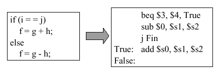
The purpose of an if statement is to provide conditional transfer of control to one or more blocks of statements, one of which is executed when its corresponding condition coded in the if-statement is satisfied. The if-statement can be implemented using the infamous go to statement, as shown in Figure 2.8.

Figure 2.8. Implementation of an if statement in
terms of high-level language using the go to statement,
adapted from [Maf01].
Example 4. Suppose we want to translate an if-statement from high-level language into MIPS assembly language. According to the method of Figure 2.8, this would be done as follows:
Note: There is a mistake in this figure - the third MIPS statement (
j Fin) should read (j False).
2.3.4. Loop Statements
Loop statements include for, while, and do-while control structures.
2.3.4.1. For-loops. A simple iterative structure is the for-loop, which has the following form:
     for index = base to target by increment
         ...statements to be executed...
     endfor
where index is a counter to be incremented, base (target) is the starting (ending) value for index, and increment is the step value that is added to index each time control passes through the loop. The for-loop is implemented in terms of the go to statement, as follows:
          index = base
   Loop:  ...statements to be executed...
          index = index + increment
          if index is greater than or equal to target goto Fin
          else goto Loop
   Fin:
This can be translated to MIPS assembly language, as shown in the following example.
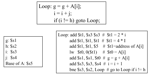
Example 5. Consider the translation of a loop from the preceding high-level language go-to format into MIPS assembly language, as shown in Figure 2.9.
Figure 2.9. Implementation of a loop statement in terms of MIPS assembly language using the go to statement, with register assignments shown on the left - adapted from [Maf01].Note that the first three assembly instructions set the value of
$t1, which holds the address of the memory element A[i]. The register$t0stores the value A[i] that is in the i-th memory element, while g is the accumulator variable and i represents the loop index. The last MIPS statement implements the loopback which branches to the labelLoopif the index i is less than the value h, which is stores in register$s2.
2.3.4.2. While-loops. A variation of the for-loop is the while-loop, which makes the execution of statements within the body of the loop contingent on the satisfaction of a condition. The while-loop has the following form in high-level language:
     while (condition)
       ...statements to be executed... ;
where condition is a logical predicate that evaluates to true or false. In each iteration of the loop, the while-loop first checks to see if condition is true. If condition evaluates to false, then the loop exits. Otherwise, the statements in the body of the loop are executed.
Example 6. Consider the translation of a while-loop from the high-level language format to MIPS assembly language, as shown in Figure 2.10.
Here, the first three MIPS statements establish the loop index, which in turn establishes the address of the memory element save[i]. (Note that "save" is being used instead of "M", to accustom you to the use of different variables to describe stored data.) In the fourth MIPS statement, the condition (save[i] != k) is checked to see if it is time to exit the loop by transferring control to the label
Exit. This is done using thebneoperation. The sixth statement comprises the body of the loop, where the variable i is incremented by the amount j. The final MIPS statement implements loopback.
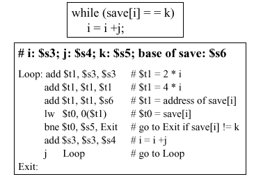
Figure 2.10. Implementation of a while statement in
terms of MIPS assembly language using the jump statement,
with register assignments shown in bold type at the top of the
lower box, adapted from [Maf01].
Analysis. It is useful to examine the code in
Figure 2.10. A cursory technique is to calculate the number N of
MIPS assembly instructions executed if save[i + m * j] does not equal
k (for m = 10), or if save[i+m*j] = k (for m between 0 and 9). In
that case, there are 7 instructions executed per iteration of the loop
(i = 0 to i = 9), plus five instructions executed when control exits
the loop (because branch to Exit is the fifth MIPS
instruction). Thus, N = 10(7) + 5 = 75 instructions.
Note: This technique of cursory analysis is acceptable in this case, because there happens to be a one-to-one correspondence between assembly and machine language instructions. However, if there were more machine language instructions than assembly instructions, then we would have to modify the number 7 in the equation N \ 10(7) + 5, to reflect that.
Optimization. There is a way to make the MIPS program in Figure 2.10 run faster, which we call partial loop unrolling. This involves repeating part of the loop body outside the loop itself, thereby allowing one to write fewer statements inside the loop. The result appears as follows:

Here, we have removed one statement from the body
of the loop shown in Figure 2.10 by moving the initial loop setup
operations and initial test for condition to a location
before the loopback point (label Loop). This allows
us to remove the j Loop statement from Figure 2.10,
combining it with the beq statement.
This partial unrolling of the loop contents and
reordering of the loop statements results in only six statements
per iteration of the loop, but there are still five statements in
the loop setup (before the Loop label). As a result,
we have N = 10(6) + 5 = 65 statements, instead of 75, to perform
the same function as Figure 2.10. This results in a relative
performance gain of 75/65 = 1.154, so the optimized code is 15.4
percent faster than the code in Figure 2.10.
2.3.4.3. Dowhile Loops. A variation of the while loop is the dowhile loop. This loop has a postcondition that is evaluated after executing the statements in the loop body, rather than the precondition of the while loop. The general form of the dowhile loop in high-level language is:
do {...statements...} while condition
where condition is a logical predicate. On the first iteration of the loop, the statements in the body of the loop are executed regardless of whether condition is true or false. Then, condition is checked, as it is at the end of every iteration thereafter.
Example 7. Figure 2.11 shows the high-level language representation of a simple do-while statement (in the upper left quadrant of the figure), followed by the implementation in terms of go-to statement (upper right). The register assignment (lower left) references the MIPS assembly code (large box at lower right).
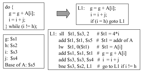
Figure
2.11. Implementation of a dowhile statement in terms of
MIPS assembly language, with register assignments shown in the lower
left-hand box - adapted from [Maf01].
Self-Exercise. (1) Repeat the analysis we gave for the while loop (Section 2.3.4.2) to determine now many instructions would be executed for A[i + m * j], for m = 10. (2) How could you use the optimization technique presented in the preceding section to make this loop more efficient? If this is not possible, show why. (A problem like this will likely be an exam question.)
2.3.5. Inequalities
In practice, algorithms and computer programs need to
compare values using inequalities such as (<) and (>). In MIPS,
such comparison is implemented via the set on less-than instruction,
called slt or slti. The MIPS
assembly instruction has the following format:
slt register1 register2 register3 ,
and implements a comparison operation that has the following functionality (in high-level pseudocode):
       if register2 < register3 then
           register1 = 1
       else
           register1 = 0
       endif
Example 8. Suppose we want to program the following high-level code fragment in MIPS assembly language:
if (g < h) then goto Less ;The following MIPS assembly code suffices:
The first statement places the value 1 in register
$t0if register$s0< register$s1, and a zero otherwise. The second statement tests whether or not there is a nonzero value in register$t0, by comparing it with the zero value stored in the register$0. If the test for inequality fails (i.e., there is a zero in register$t0), then control is passed to the next statement. Otherwise, control is passed to the instruction in memory referenced by the labelLess.
An alternate form of the slt instruction
is slti (set on less-than, immediate mode), which
allows comparison of register contents with a constant value that is
hardcoded into the assembly language instruction. The
slti instruction has the following format:
slti register1, register2, constant
where constant is a hardcoded constant value.
Example 9. The slti instruction is useful in loops. For example, if g is a loop index, and we want to implement the following high-level code fragment:
if (g >= 1) goto Loop;then the following MIPS instructions would be employed:
Here, the first instruction says that register
$t0= 1 if g < 1, where the constant 1 is hardcoded into the instruction (hence, the use of immediate addressing). The second instruction transfers control to the labelLoopif g is greater than or equal to 1.
For unsigned number representations, which we shall
discuss later in this course, the sltu and
sltiu instructions are employed. These function
similarly to slt and slti.
Relational operators other than equals and not-equals are unsupported in MIPS assembler. Instead, the following constructs can be used to create assembly language representations of the remaining relations:

We call these pseudoinstructions because while they are not directly supported by the MIPS assembler, they can be constructed from other MIPS assembly language instructions.
2.3.6. Case and Switch Statements
The high-level language statements called case or switch select a statement or group of statements to be executed based on the value of a key variable. In Figure 2.12, the high-level code is expressed in terms of the C-language switch statement (upper left-hand box). The arrow pointing down to the if statement (lower left-hand box) shows how the switch statement is translated into a series of if statements, which we already know how to implement in MIPS assembly language (per Section 2.3.3). The assembly code is shown in the right-hand box.
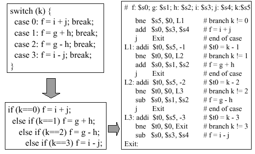
Figure
2.12. Implementation of a switch statement in terms of
MIPS assembly language, with register assignments shown at the top of the
right-hand box - adapted from [Maf01].
2.3.7. Jump Tables
It is possible to store in memory the addresses of
machine language instructions to which control is to be transferred
(for example, by a conditional branch). Thus, let a jump table
be comprised of registers that contain the memory addresses of machine
language instructions that are referenced by labels L0 through L3. We
use the MIPS instruction called jr (for jump
register to implement the jump to the address contained in a given
register that is referenced by the jr instruction.
Figure 2.13 illustrates this process.
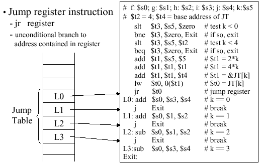
Figure
2.13. Implementation of a jump table in memory using
MIPS assembly language, with register assignments shown at the top of the
right-hand box - adapted from [Maf01].
2.3.8. Procedure Support
In order to run programs that are comprised of multiple procedures, the MIPS ISA must support memory mapping and C or C-like function definitions and encapsulation, as well as stack-based execution and some type of compilation. In this section, we discuss these concepts and how they are implemented in MIPS.
2.3.8.1. Memory Map. In order to keep the storage of data and instructions for a given program orderly, MIPS uses the memory map illustrated schematically in Figure 2.14. Here, there is a 4MB reserved space starting at hexadeciaml address 0x00000000 to the text segment, which starts at 0x00400000. The reserved space is used for system bookkeeping and other functions, while the text segment stores a program's instructions.

Figure 2.14. Layout of memory in MIPS architecture, where
$gp denotes global pointer - adapted from [Maf01].
You can read about this further in Section A.5 of your textbook
[Pat98].
The data segment begins at 0x10000000 and is divided
into two parts. The static data segment contains objects whose size
is known to the compiler and whose lifetime extends throughout the
program's execution. By lifetime, we mean the interval during
which a program can access data. In contrast, dynamic data is
allocated by the program as it executes. For example, the C
malloc function allocates memory dynamically by finding
and returning a new block of memory using operating system utilities.
The program stack segment resides at the top of the address space, starting at 0x7FFFFFFF. The stack is a dynamic structure that stores values generated by different operations throughout the course of a program's execution. Since the contents of the stack are not known at compile time, the stack size varies, hence the large memory space alloted to it.
This three-part division of memory (text, data, and stack segments) has the advantage that the dynamically expandable segments (dynamic data and stack) are as far apart as possible, but are positioned to use the entire program's address space, if necessary.
2.3.8.2. Data Segment. Two instructions
(lui and lw) are needed to access the data
segment, as shown in Figure 2.15. To avoid repeating the lui insturction at every load and store, MIPS typically dedicates a register called
$gp (global pointer) to the static data segment. This register
contains address 100008000016, so load and store instructions
can use their signed 16-bit offset fields to access the first 64KB of
the static data segment.
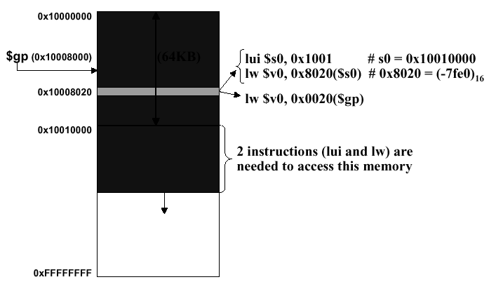
Figure
2.15. Accessing an entry in the data segment, adapted from [Maf01].
Figure 2.15 illustrates the rewriting of the instruction pair
        lui $s0, 0x1001
        lw  $v0, 0x8020($s0)
using the global pointer, as the single instruction
lw $v0, 0x8020($gp)
Additionally, $gp renders more efficient the addressing of locations 1000000016 through 1001000016 than other heap locations. MIPS compiler usually stores global scalar variables in this area because these variables have fixed locations and fit better than other global data such as arrays. (The scalars are smaller and can thus be packed more efficiently into limited memory space.)
2.3.8.3. Support for C Functions and Procedures. The C language (and many other high level languages) are modularly structured, being comprised of numerous functions, procedures, or subroutines. These functions are called from the main program, and can be called by each other, leading to a transfer of control that is diagrammed with arrows in Figure 2.16.
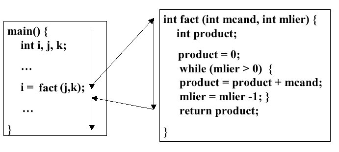
Figure
2.16. Calling sequence in C, adapted from [Maf01].
A key implementational question pertains to the bookkeeping information that the compiler must keep track of. In the C calling sequence as implemented in MIPS, the following information is accounted for:
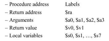
The procedure address includes the labels that
reference the procedure, and their addresses. The return address
points to the location in memory that control is transferred to
after the called procedure completes. The argument registers
contain the values referenced by the formal arguments of the called
procedure. The return values are what is returned by the called
procedure through the return statement when the procedure
completes. If the called procedure is declared a void procedure,
then $v0 and $v1 are empty. As discussed previously $s0 through
$s7 are used to store values referenced by variables that are local
to (within the scope of) the called procedure.
Because procedures are dynamic, procedure call frames (PCFs) are used to store this bookkeeping information. Typically a PCF contains arguments, save registers, and local variables. If a machine has a small number of registers, then the state S of the registers must be saved prior to calling a subordinate procedure. Otherwise, the calling procedure or program's state will be obliterated. After the called procedure completes, then the machine is restored to S, augmented by the values returned by the called procedure. The register conventions shown in Table 2.1 apply to called procedures (termed callees) as well as to the calling procedure or program.
2.3.8.4. The Stack. The stack is where the stack frames, also termed Procedure Call Frames or PCFs, are temporarily stored in memory. The stack begins at address 0xFFFFFFFF and can be expanded upward. However, 0xFFFFFFFF up to 0x7FFFFFFF is reserved space. Thus, the stack frame corresponding to the main program begins at 0x7FFFFFFF, as shown in Figure 2.17a.
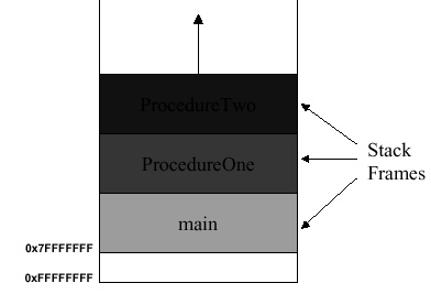
(a)
(b)
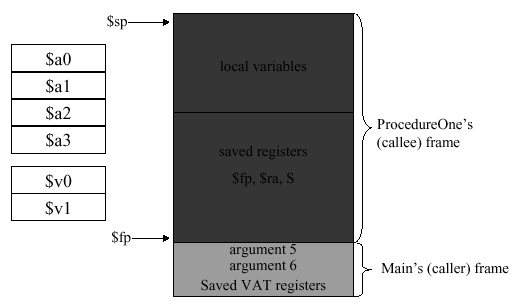
Figure 2.17.
(a) MIPS stack and (b) stack frames for called procedure, adapted from
[Maf01].
In Figure 2.17b is shown the stack with the main
program's stack frame and the called procedure (callee) frame. In
this case, the callee frame ranges from address $fp to
$sp (the stack pointer, which points to the furthest
extent of the stack). The argument registers ($a...) and the return
value registers ($v...) are stored in the callee's stack frame. Extra
arguments that cannot be stored in $a0 through
$a3 are stored in the calling procedure's stack frame.
Additionally, memory locations that store the calling program's
(caller) state are referenced by their addresses stored in the
caller's stack frame (denoted by VAT in Figure 2.17b).
The following process occurs when a procedure is called:
- Step A. Immediately before the caller invokes the callee
- Pass the first four arguments of the callee to registers
$a0through$a3 - Push the extra arguments (if there are more than four args) on the stack
- Save to memory the caller-saved registers (
$a0-$a3;$to-$t9) - Execute
jal(jump and link) to jump to the callee and save the return address in$ra - Allocate memory for the stack frame of size fsize as
$sp=$sp- fsize - Save to memory the callee-saved registers (
$s0-$s7;$fp,$ra) - Increment the frame pointer to reflect the callee's requirements
$fp=$fp+ (fsize - 4) - Place the returned value(s) in register(s)
$v0($v1) - Restore all callee-saved registers
- Pop the stack frame for the callee, as
$sp=$sp+ fsize - Restore
$fpto its former value (stored in Step B.2, above) - Return by jumping to the address in
$ra
Step B. Just before the callee starts executing
Step C. Immediately before the callee returns to the caller
We can better understand this sequence of operations if we analyze a simple example.
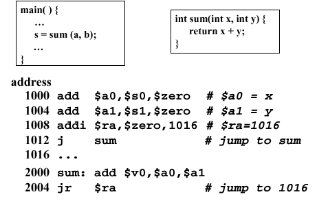
Example 10. Consider the following example of a program that calls an addition function
sum(x,y):
Here, the first two
addinstructions put the arguments ofsuminto the argument registers$a0and$a1. Then, the return address is set at 1016, the address of the instruction after the subsequent jump. The jump instruction jumps to the labelsum, which is references memory address 2000. Here, the local variables x and y, whose values are stored in the argument registers$a0and$a1, are added and the result put in the return register$v0. Then, the instructionjr(jump register) is executed to pass control to the return address ($ra= 1016, which was set in the third instruction).
Alternate Approach. The preceding process can
be made more efficient by eliminating one instruction in favor of the
jal (jump and link) instruction. This should actually be
called the link and jump instruction, since it automatically
stores the address of the next instruction in $ra, then jumps to the
label specified in the instruction syntax:
jal label
Jump and link is a J-format instruction, which would be used in the preceding example to implement the following code:

Self-Exercise. In the preceding example, all other things being equal, what is the efficiency realized by substituting the
jalinstruction for thejinstruction? Justify your answer quantitatively.
The jal instruction is also useful for
nested procedures, where one procedure is called from inside another.
The following code fragment is illustrative:
       int sumSquare(int x, int y) {
         return mult(x,x) + y;
      }
This code fragment is rendered in MIPS assembler as follows:
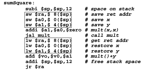
Here, instead of using addition instructions to store values in registers, we use load and store instructions to perform very fast memory I/O to save and restore variables. The boxed instructions show how arguments are the return address are saved in a very efficient manner. The addition instructions require the ALU to be activated - load and store do not require the ALU, which is much slower than register I/O. Since we perform many I/O operations for procedure calls, mainly in saving and restoring the procedure state via the stack frame, we want to make the common case fast and use the most efficient means of handling arguments and jump addresses that we possibly can.
2.3.8.5. Stack and Recursion. The final perversion of the previous development sequence (procedures => multiple calls => nested procedures) occurs when we have recursion, where a procedure can call itself many times (in the worst case, infinitely). This causes a large number of procedure call frames to be stored on the stack. It is thus possible to run out of stack space. We call that undesireable condition stack overflow. There are several ways to avoid stack overflow, including virtual memory (paging stack contents to disk), which we will discuss later in this course. In the meantime, consider the following example.
Example 11. Recall that the factorial of a number N can be computed as
N! = N · (N-1) · (N-2) · ... · 2 · 1 .
Thus, the factorial is recursive. As a result, a routine
fact(x)that computes the factorial of its integer argument x could be written as:
fact(x) = x·fact(x-1)·fact(x-2)· ... · 1 .This implies the following C code for the factorial function:
        main(){
           int f;
           f = fact(10);
           printf("Fact(10 = %d\n",f);
        }

        int fact(int n){
           if (n < 1)
              return(1);
           else
              return(n * fact(n-1));
        }
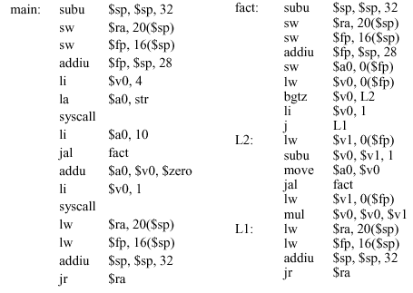
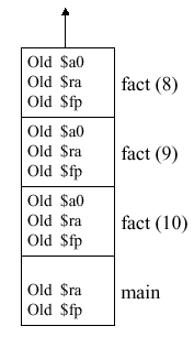
As a result, the stack will be loaded with stack frame for the
main()routine, followed by the stack frames forfact(10),fact(9), ...,fact(1), in that order, as shown in Figure 2.18a. This is a representation of the stack when the recursion is "wound up", i.e., all the calls tofact(n)have been made. Then, the stack is "wound down" by evaluating each call tofact(n), using the stack frames pushed onto the stack when the stack was wound up. Thus, the calls tofactwill be evaluated in the orderfact(1),fact(2), ...,fact(10), followed by the evaluation of the remainder of themainprocedure. This is done by (1) popping the stack frame for a given call off the stack, (2) evaluating the call, then (3) going back to the stack for the next stack frame. When the stack is empty, the program has been evaluated. The MIPS assembly code for this process is shown in Figure 2.18b.
(a)
(b)
Figure 2.18. (a) MIPS stack for the factorial programmainshown above, and (b) corresponding assembly code, adapted from [Maf01].Self-Exercise. The program shown in Figure 2.18b is explained in detail in Appendix A of the text [Pat98], pages A-26 through A-29. Please familiarize yourself with this example, as well as the example that computes the Takeuchi benchmark, which is discussed in detail on pages A-29 through A-32.
In summary, MIPS has several conventions that make
procedure calls feasible. First, the callee can use VAT registers
freely. Second, the caller can use the S-registers without having
his values overwritten. Third, you can use the stack to save your
data or instruction addresses, provided that you leave it the way
you found it (i.e., pop off the things you pushed onto the stack
after you are done using the stack). Fourth, the register conventions
should be observed, to keep memory access consistent. Fifth, MIPS
provides instruction support in terms of the jal and
jr instructions, where jal operates on a
label, and jr operates on a register (e.g., $ra).
2.4. Number Representations, Data Types and Addressing
Reading Assignments and Exercises
In this section, we discuss theoretical and practical foundations for representing numbers in digital computers, including MIPS. We then show how different types of data are represented and referenced (via addresses) in MIPS.
2.4.1. Number Representations
In Section 1, we showed how different number systems (e.g., binary, decimal, hexadecimal) could be used interchangeably to represent a wide range of integers. Computers used fixed precision number representation. This means that if a number can be represented using N binary digits, then the range of possible values for that representation is -2N-1 to 2N-1 - 1.
Because of the precision problem, the laws of continuous algebra do not always hold in computer arithmetic. We will shortly see why this is so. First, let us consider issues associated with computer representations. Note that bits can be used to represent anything - text, characters, images, colors, etc. However, N bits can only be used to represent a maximum of 2N distinct (unique) objects.
2.4.1.1. Signed Magnitude Encoding. Number representations in binary arithmetic tend to be problematic if you want to represent negative numbers and zero. For example, one can used signed magnitude encoding, which represents a number (e.g., -37) as a binary number (e.g., 1x0100101). Here the minus sign is represented by a leading 1. If a positive number is thus represented, the leading digit is zero. (Note that the leading digit is called the most significant bit or MSB.) The problem with signed magnitude representations is that there are two representations for zero, namely -0 (1x0000) and +0 (0x0000). This makes arithmetic circuits compilcated. Hence, signed magnitude encoding was abandoned early in the development of computer arithmetic.
2.4.1.2. Ones Complement Encoding. Numbers can be encoded using ones complement, which makes arithmetic circuits simpler. For example, 710 = 001112, but -710 = 110002. Thus, positive numbers have leading zeroes, while negative numbers have leading ones. Unfortunately, there are still two zero representations (0x0000 and 0x11111).
2.4.1.3. Twos Complement Encoding. An improvement over ones complement is realized by making each positive binary number x start with zero and -x = not(x) + 1. For example,
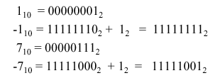
Thus, positive (negative) numbers can have infinitely many leading zeroes (ones). Twos complement numbers have some interesting properties, for example, the negation property. Let x' denote the negation of binary number x (e.g., if x = 1010, then x' = 0101). The following assertion holds:

Example 12. Consider the following conversion from the decimal number 4 to -4, then back to 4:
The steps are shown in blue, with the "trick" of adding one to the inverted result shown in red (on the left-hand side), with its result shown in red (on the right).
Complementary representations present some interesting implementational issues. If one does not differentiate between signed and unsigned numbers, comparisons can be problematic. For example, if x = 1110101 and y = 0110101, then x > y if the representation is unsigned, but x < y if the representation is signed. Thus, one must consistently use signed or unsigned number representation in a computer architecture.
Another issue is sign extension when converting from a reduced-precision representation to a higher precision representation. For example, supposed we have an eight-bit twos complement number x = (1111 1100), that we wish to convert to a 16-bit representation. Because positive (negative) twos complement numbers have an infinite number of leading zeroes (ones), we can simply view any N-digit twos complement representation as a leftward truncation of the actual (infinite-length) twos complement representation. Thus, expressing x in 16-bit format is merely a matter of filling the more significant bits with the leading bit of the low-precision form, e.g., x becomes (1111 1111 1111 1100)). This also holds for extension of leading zeroes, which is another reason that twos complement numbers are useful in computing.
2.4.2. Datatypes
As we stated in the introduction (Section 1), one of the big ideas of computer science is that data is pliable - it can be anything that the program requires it to be. In general-purpose computing or with high-level languages, data can include integers, floating point numbers, characters, strings, dates, currency information, text, objects (e.g., abstract datatypes), blobs in graphics, double precision numbers, as well as signed or unsigned number representations (as discussed in the previous section).
MIPS provides support for numeric datatypes such as integers (signed and unsigned representations) and floating point numbers, as well as strings, memory addresses (pointers), and instructions. MIPS also supports 16-bit constants (immediates), halfwords (16 bits), and bytes (8 bit).
As shown in Figure 2.19, the lb (load
byte) instruction expressed as lb $s1, 4($s0) transfers
data from the address contained in register $s0, with an
offset of 4 bytes, to the register $s1. This can also be
accomplished with the lbu (load byte unsigned)
instruction, as shown in Figure 2.19.

Figure
2.19. Example of the load byte instructions, adapted from
[Maf01].
Another application for which MIPS can be used is
string manipulation, which helps illustrate the use of lb
and sb instructions (byte I/O). The following example
is illustrative.
Example 12. Suppose we want to copy string x to string y. We can use the C language routine
        void strcpy(char x[ ], char y[ ]) {
           int i ;
           i = 0 ;                        # initialize loop counter
           while ( (x[i] = y[i] ) != 0)   # check for end-of-string
             i = i + 1 ;                  # increment loop counter
        }
Here,
strcmpexits when x[i] and y[i] are unequal, i.e., when a difference is found in the characters of xy at a given position i. This is implemented in MIPS, as follows:
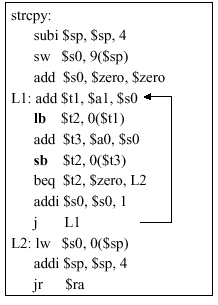
Here, the routine
strcpyhas three parts: (1) the prologue, which comprises the first three statements that set up the stack and initialize the$s0register; (2) the body that contains the MIPS representation of the while loop; and (3) the epilogue that resets the address space (stack pointer) and jumps to the return address (which we assume was set prior to jumping tostrcpylabel).Assume that base addresses for arrays x and y are found in argument registers
$a0and$a1, while i is in$s0. In the prologue, the stack pointer is adjusted and$s0is saved on the stack. The register$s0is then set to zero, and the loop begins at label L1. The address of y[i] is formed by adding offset i (in$s0) to y. Note that the offset need not be multiplied by 4, as in previous examples, because the characters in x. and y are an array of bytes, not 32-bit words. To get the character in y[i] from memory to register, we use thelbinstruction, which puts the character into$t2.The next step is to transfer the character from
$t2to memory. To do this, we first put the address of x[i] in$t3, then usesb(store byte) instruction to transfer the character in$t2to that address. If the character is a zero (end-of-string character in C), then we exit the loop and go to label L2. Otherwise, the loop index is incremented with theaddiinstruction, and we return to L1. In the epilogue, the stack pointer and$s0are reset, and control is transferred to the return address.
In actual C-language string manipulations, pointers are used, as discussed in Section 2.6. This avoids the overhead associated with loop index manipulation.
2.4.3. Addressing
MIPS has several types of addressing, including immediate mode for constant-valued operands. As stated in Section 2.2.3.1, the common case is that small constants are used frequently. Thus, in order to make the execution of operations with small constants fast, we (1) put the constants in memory then (2) load them into registers. A second type of addressing puts constants directly into the assembly language instruction (e.g., hardcoded constants). We address these constants in immediate mode, for example, the following add-immediate instruction:

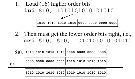
Immediate mode can be useful for purposes other than arithmetic. For example, suppose we want to load a 32-bit word into a register, but MIPS supports only 16-bit constants. The trick here is to first load the higher-order bits using the load upper immediate instruction
lui $t0, 10101010101010101010
which loads the constant (second operand) into the upper half (more significant 16 bits) of $t0. We then load the remainder of the lower order bits using the or-immediate instruction:
ori $t0, $t0, 10101010101010101010
which works as shown below:
MIPS has several additional addressing modes,
including data and instruction modes. Data addressing
features register addressing (the fastest and shortest mode), base
addressing (for operands in memory, e.g., lw $t0 20($t1),
and immediate addressing that hardcodes a constant directly into an
instruction. We have already studied each of these modes.
Instruction addressing modes include PC-relative addressing (for branches) and pseudodirect addressing (for jumps). The term PC means program counter, which is a special-purpose address register that points to a given instruction in the instruction sequencer.
In PC-relative addressing, the address is the PC + C · 4, where C denotes a constant hardcoded into a branch instruction. This allows the program address space to be (in principle) as large as 232 instructions. If we simply used PC, only 216 instructions would be allowed (16-bit address space), which is far too small for modern programs.
In pseudodirect addressing, the address is PC[31:28]
(upper six bits of the PC address) concatenated with the 28-bit word
represented by the 26 bits of address in the jump instruction. This
is useful for long jumps (not the common case), and can be inserted by
the MIPS assembler, as follows. In practice, the assembler performs
this insertion of a large jump (to a far target address) by
converting a beq branch to a bne branch, as
shown below.
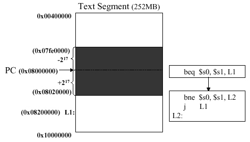
Here, the current PC is outside the memory segment in
which local activity occurs (the shaded region in the preceding
illustration). The 26-bit field in the jump instruction is also a
word address, i.e., it represents a 28-bit byte address. To make up
the remaining four bits, MIPS uses the upper four bits of the PC. As
a result, the loader and linker must be careful to avoid placing jumps
across an address boundary of a 256MB segment. Otherwise, the jump
must be replaced by a jump register instruction, where the full 32-bit
address must be loaded into the register using an immediate-mode
instruction like that shown in the ori example, above.
2.5. MIPS Programs
Reading Assignments and Exercises
MIPS supports translation of high-level languages (HLL) such as C to assembly language, then to object code and executable code. In this section, we examine this process, shown schematically in Figure 2.20.
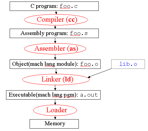
Figure
2.20. Example of MIPS compilation sequence, adapted from
[Maf01].
Here, the C source file foo.c is
compiled using the C compiler (Unix command cc),
to yield an assembly language program foo.s. This
program is input to the MIPS assembler (Unix command
as), producing an object (machine language) module
foo.o. The linker (Unix command ld)
links a library lib.o with the object module to produce
the executable file a.out. When the executable is
invoked (via the Unix command a.out), the loader
puts the executable code into memory, and the program is run.
The assembler, which is of concern to this course, performs the following tasks:
- Reads and executes directives for special treatment of
input (per Section 2.5.1)
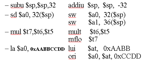
- Replaces pseudoinstructions (shown below in the
left-hand column) with blocks of instructions supported by
MIPS (shown below to the right of the pseudoinstructions),
for example:
- Produces machine language file, as discussed in
Section 2.5.2; and
- Creates an object module with filename ending in ".o", whose structure is overviewed in Section 2.5.3.
We next consider assembler directives, which are somewhat like preprocessor commands in C.
2.5.1. Assembler Directives
The MIPS assembler supports the following directives, which do not produce machine language code, but merely control the functions of the assembler:
.align n- Align the next datum on a 2n byte boundary.text- Put subsequent items in user text segment of memory.data- Put subsequent items in user data segment of memory.global sym- Set the access permissions on the symbol table so it can be referenced from other files.asciiz str- Store the stringstrin memory.word w1..wn- Store the subsequent n 32-bit quantites in successive memory words.byte b1..bn- Store the subsequent n 8-bit quantites (bytes) in successive memory words.float f1..fn- Store the subsequent n floating-point values in successive memory words
Another assembler feature is absolute addressing, which is described as follows. Absolute addressing supports relocation editing by implementing load/store operations to variables in static memory, conditional branches, jump instructions, and direct references to data, as shown below:
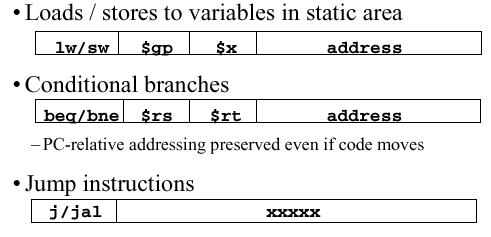
In some cases, these references cannot be determined at assemble time (when the assembler translates MIPS code to machine language), so temporary data structures are created, as described in the following section.
2.5.2. Production of Machine Language
In the simplest case, machine language instructions can be directly produced from MIPS assembly code. Here, the basic information needed to translate the assembly instruction to one or more machine language instructions is already within the instruction. Arithmetic, logical, and shift instructions are in this category.
With conditional branches, some delay is encountered, since pseudoinstructions (not directly supported by the MIPS assembler) have to be translated first into their assembly language equivalents (instructions directly supported by MIPS). After all the pseudo instructions have been translated, it is possible for the assembler to make a second pass, where the machine language instructions are counted up, and the branch target addresses (where the branch instructions transfer control to) can be calculated. The PC-relative addressing mode is useful for this step of machine language production.
Direct (absolute) addressing presents a problem, due
to jumps (j and jal instructions), as well
as direct (absolute) references to data. These cannot be determined
at this step of the assembly process, so we need to create two tables:
the symbol table and relocation table.
The symbol table contains a list of object
s in the assembly language program that may be used by other
files. This includes labels, for function calling, and
data (e.g., anything in the data directive or
variables that are to be accessedacrossed files. On the first pass,
the assembler records label-address pairs. On the second pass,
machine code is produced. Thus, it is possible to jump to a subsequent
label without declaring it first.
In contrast, the relocation table is a list of
objects for which the assembled program needs addresses. This
includes any label jumped to (j or jal
instruction), whether internal or external (including library files).
Also, the relocation table contains any piece of data specified within
the program.
2.5.3. Structure and Creation of Object Module
The object module contains the following information:
- Object File Header contains the size and position of
the specific partitions of the object file
- Text Segment is the place where the machine code resides
- Data Segment contains the binary representation of data
in the source file
- Relocation Information identifies lines of code that
need to be processed further (e.g., direct addresses)
- Symbol Table contains the list of the current program's
labels and data that can be referenced
- Debugging Information specifies link points and entry points to various routines, libraries, etc.
2.5.4. Linker
The linker combines object (.o) files into an executable file. This enables separate (independent) compilation of files. However, only the modified files are typically recompiled. For example, Windows NT source code has over 30 million lines of code, so we want to perform incremental compilation on this large corpus of code, rather than attempting to compile it all at once.
The linker also edits the links in the
jal (jump-and-link) instructions, substituting addresses
where appropriate. This is why the linker used to be called the
link editor.
The linker performs the following steps:
- Step 1. Assembles the text segments from each .o file to
get a composite of all the code in the program
- Step 2. Concatenate the data segments from each .o file
and append to the end of the text segment
- Step 3. Resolve the references by going through the relocation table and processing each entry, filling in all absolute addresses. Notify the user of any unresolvable references.
There are four types of references that need to be resolved, which are:
- PC-relative references such as branch instruction
targets, which are never relocated
- Absolute addresses such as jump targets, which are always
relocated
- External references such as jump-and-link targets,
which are always relocated; and
- Data references (e.g., from
luiandoriinstructions), which are always relocated
The linker assumes the first word of the first text segment is at 0x00000000. Since the linker knows the length and ordering of each text and data segment, the linker can calculate the address of each internal or external jump target as well as the address of each piece of data being referenced.
2.5.5. Loader
The linker produces an executable file that is stored on disk. The loader puts the executable code in memory and starts it running. As a result, the loader is often thought of as a part of the operating system. The loader performs the following functions:
- Read header to determine the size and the text and
data segments
- Create new address space for the program that is large
enough to hold the text and data segments, and also the stack
- Copy instructions and data from executable file memory
- Initialize the machine registers, for example,
$sppoints to the first free stack location - Jump to the initial routine that copies the program
arguments from the stack to the registers, then sets the PC
- When the main routine returns, the start-up routine terminates the program execution with a system call.
Thus, the loader can be thought of as the runtime module.
In summary, the compiler converts a single HLL file into an assembly language file. The assembler translates pseudoinstructions, converts what instructions it can directly to machine language, and creates a checklist for the linker called the relocation table. This changes each source file into an object file. The linker combines several object files (including libraries), and resolves absolute addresses. The loader loads the executable produced by the linker into memory and begins program execution.
2.6. Pointers and Arrays
Reading Assignments and Exercises
In this section, we discuss in greater detail the issues surrounding pointers (addresses) and contiguous regions of memory that store values in arrays (as discussed in Section 2.6.1). Salient implementational issues include argument passing as well as the lifetime and scope of storage (Section 2.6.2). Uses of pointers include pointer arithmetic (Section 2.6.3) and the use of pointers with arrays (Section 2.6.4).
2.6.1. Basic Pointer Concepts
Definition. A pointer is a variable that contains the address of another variable.
In practice, a pointer can be thought of as the HLL equivalent of a machine language memory address. We use pointers to express a program's functionality more compactly and efficiently, and to perform memory operations that cannot be done another way. Unfortunately, pointer mis-use comprises the largest amount of bugs in a typical program, with the following two errors predominating:
- Dangling Reference - when a pointer points to a
memory location that has been prematurely freed
- Memory Leaks - when a memory location has been freed too late, or not freed at all, and a pointer still should reference it.
As a result of these defects, a program must be restarted frequently to avoid accumulation of dangling references or leaks.
Let us consider several example of pointer use in the C language.
Suppose a variable v has value 100, and is
located in memory at address 0x10000000. The unary operator (&) gives
the memory address of v, for example: p = &v;
while the (*) operator gives the value that pointer p points to,
for example: value = *p. We call the (*) operation
dereferencing, and it is important in assembler, as shown below:

Thus, the (*) operator, used to the right (left) of the equals sign, can implement a load (store) operation.
Example 13. Assume that the variable c is an integer, has value 100, and resides in memory at address 0x10000000. Further assume that the pointer p is stored in register
$a0, and that the variable x is stored in register$s0. The following code fragment is illustrative of dereferencing. the numbered code is C language, with assembly instructions listed below:
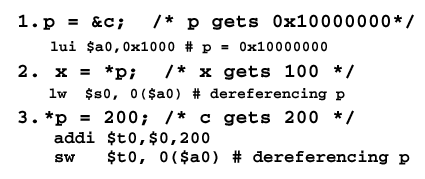
The first item puts the address of c in p. The second item dereferences p to put the value stored at that address in x, which is a synonym for
$s0. Finally, the memory location whose address is in p receives the value 200. Note that theaddi(add immediate) operator is used to put the value 200 in register$t0, then the contents of$t0are stored in the location pointed to by$a0(which contains the value of p).
We already know about memory leaks and dangling pointers. This concept of data persistence leads us to ask how long pointers last within a program. We discuss this in the following section.
2.6.2. Storage Lifetime and Scope
There are three types of pointer allocation that affect the storage lifetime and scope of the pointer:
Automatic (stack allocated) pointers typically reference local variables of a function. These pointers are volatile, in the sense that they are created at the function call, and are released (freed) upon return to the calling procedure. As a result, the scope of the pointer is the called function.
Heap allocated pointers are created by in invocation to the
mallocroutine, and are released when explicitly freed. Their scope can be local or global to a given program. If not freed, they can cause memory leaks.External (static) pointers are created at the program's invocation, and exist for the length of the program. Thus, their scope is global to the program.
We will next examine how we can manipulate these different types of pointers to achieve different addressing modes.
2.6.3. Pointer Arithmetic
Various types of arithmetic operations can be performed on pointers. For example, addresses can be incremented and decremented, assigned, dereferenced, etc. The following example is illustrative of memory operations, where the array z contains various values referenced by pointers:
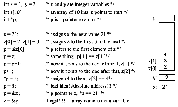
Note that there are two instances of mistakes using
pointers. The first involves hardcoding a direct address into a
C-like program - a very bad idea, for two reasons: (1) one can
reference a protected part of memory where system resources reside, or
(2) future operating system or compiler revisions might not support
such a modification. The second error, which is an illegal operation,
involves trying to make the entire array z point to the scalar
variable y, using the statement z = &y.
Example 14. As a further illustration of pointer usage, consider the following C code:

which is translated into the following assembly language instructions:
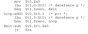
Note that the argument in
$a0dereferences the actual argument variable (a string s), so that the pointer p points to the characters in the argument. Theaddiinstruction is used to increment p so it points to the next character in the string. In both cases, thelbu(load byte unsigned) instruction is used to effect the dereferencing.After the loop completes, the length of the string is equal to the different p - s. This is yet another example of pointers can be used both as addresses and as counters. This makes the assembly code much more compact, and thus produces fewer instructions.
When using pointers in an argument list, we implement the latter of the follwoing two argument passing modes:
Call by Value passes a copy of the item in a given argument position to the function or procedure.
Call by Reference passes a pointer to a given argument to the function or procedure.
In practice, it is easier to pass single word variables by value, since this avoids the overhead of pointer manipulation.
2.6.4. Use of Pointers in Array Manipulation
Suppose we have an array (e.g., a[100]) in the argument list. This can be passed in two ways. The Pascal language uses call-by-value (e.g., copies the entire 100 words of a onto the stack). This is prohibitively costly for large arrays. In contrast, C (call-by-reference) passes a pointer (one word long) to the array a, with the pointer being stored in a register for fast manipulation.
There are four versions of array manipulation for a binary arithmetic operation (e.g., adding arrays a[100] + b[100] and putting the result in c[100]).
- Result array is passed to the function or procedure.
- The result is put in a local array on the stack, and a pointer to the local array is passed to the function or procedure.
- The result array is allocated on the heap.
- The result array is declared static.
We discuss each of these techniques with an example,
as follows. Each example assumes that we have an array addition
routine called sumarray.
Example 15 (Array passed to Function). Given the following C code:
        int a[100],b[100],c[100];
         sumarray(a, b, c);
the meaning of this C calling convention is
sumarray(&a[0], &b[0], &c[0]);If we want to use assembly language to pass pointers that reference arrays, then we need to compute the address size (.e.g, a 100-element array requires 400 bytes of storage in MIPS). This is done as follows:

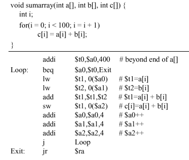
Note that the
addiinstruction is used to set the base addresses, with a[0] starting at $gp. Then, thejalinstruction is used to invokesumarray, as discussed previously. The C code and compiled assembly code for the functionsumarraylooks like this:
The second method is to put the result array on the stack as a local array, then return the pointer to that array to the function or procedure, as follows.
Example 16 (Array Pointer passed to Function). In the following code, notice how the prologue portion of the assembly code uses the
addiinstruction to allocate space for the result array c, set the pointer, and pass it to$v0(the first result register):
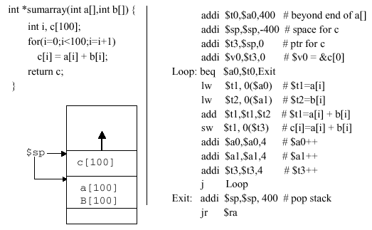
The loop is straightforward, and begins with a limits check that branches to the exit point if the loop index (in register
$a0) is exceeded. Next, the operands a[i] and b[i] are respectively loaded into registers$t1and$t2, the addition operation is performed, and the result is stored in memory location referenced by$t3with zero offset. The input operand pointers and result pointer are reset, then the jump instruction transfers control to the loopback point.
The next two techniques are not used very often. Placing the array on the heap renders the array information not reused unless freed. This leads to memory leaks. Using static arrays is memory-consumptive, but tends to be employed in C libraries.
Example 17 (Result Allocated on Heap). Given the following C code:
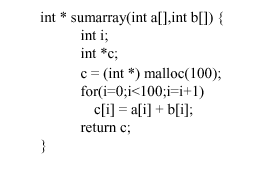
the compiled version is as follows:
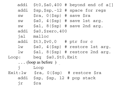
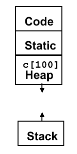
Here, the heap allocation is accomplished by the call
jal malloc, which is necessarily bracketed by the saving and restoring of the arguments. Note the many additional lines of code that are required beyond those shown in Example 16. As a result, memory allocation looks like this:
The final example uses static memory for array storage.
Example 18 (Static Memory). Given the following source code fragment:
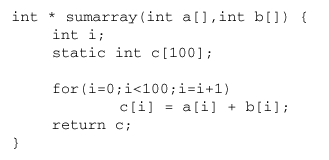
Note that the
staticdirective causes the array to be in static memory, as shown below:
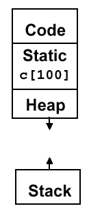
As a result, the array c will be changed next time
sumarrayis invoked. This method is typically used in C libraries, and is very expensive from the viewpoint of memory usage.

