Purpose
Learn how to use affine transformations to position objects in 3-space.
Resources
- OpenGL Transformations and Matrices — moving, scaling, and rotating objects.
- OpenGL Shading — lighting the scene.
- GLFW Input Handling — adding keyboard inputs.
- GLM — convenient OpenGL mathematics library.
- GLSL Data Types — useful for shader programming.
Set Up
- Use one of: OpenGL or WebGL.
- For OpenGL, use the supplied code base.
- For WebGL, starter code is not provided.
Task 1: Grid (5 points)
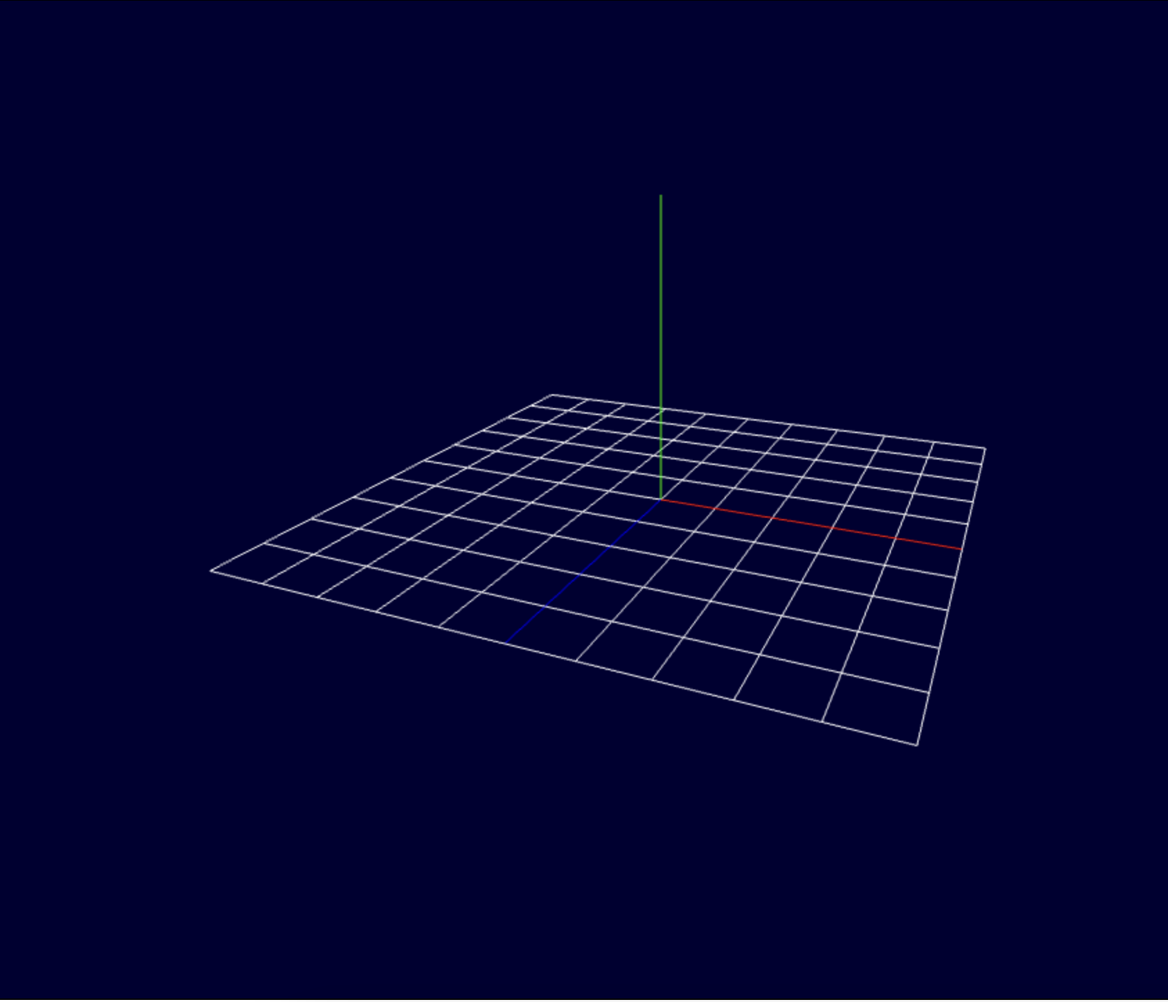
Draw an integer grid on the Y = 0 plane for the rectangle from (-5, 0, -5) to (+5, 0, +5).
Draw the positive portion of each axis, with length 5:
- X axis: red
- Y axis: green
- Z axis: blue
Task 2: Camera Rotations (5 points)
- Use perspective projection.
- Place the camera so that you can see the whole scene. Use
glm::LookAtto generate the View matrix. - Press C to select the camera. (This sets the context of subsequent ← and → commands)
- Use ↑ and ↓ to rotate the camera along the red circle orthogonal to the equator.
- Choose the up direction so the camera always points to the origin. Test this by moving the camera across the north pole.
Task 3: Draw the Robot Arm (25 points)
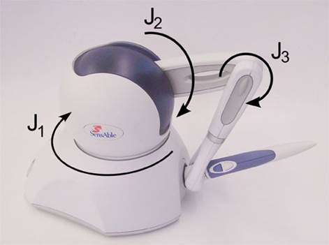
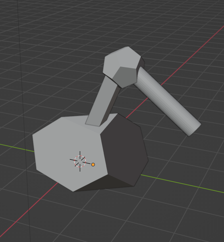
The robot arm consists of the following parts:
- Base: truncated tetrahedron placed on the X–Z plane.
- Arm 1: rectangular box emanating from and hinged at the center of the base.
- Joint: dodecahedron of appropriate radius at the other end of Arm 1.
- Arm 2: cylinder connected to the center of the joint.
- Before assembling in the code, place the parts onto the grid, and show them shifted to not overlap.
Geometry and models
- Create triangulated objects in
.objformat, for example by using Blender. - Hint: For later use, load the models so that their model coordinate origin is the pivot (rotation center) point.
- Translate and rotate the models within your project to their world coordinates.
- Load or generate correct normals for later use.
- To load
.objfiles, you can use your own loader OR tinyobjloader OR adjust the supplied OBJ loader:bool loadOBJ( const char *path, std::vector<...>& out_vertices, std::vector<...>& out_uvs, std::vector<...>& out_normals, std::vector<...>& out_indices ) - Hint: You may want to familiarize yourself with obj reader errors
What to Submit
- Your modified source files — CPP, shader, HTML, OBJ, as appropriate. File paths used to load models must be relative to the source directory; do not use absolute paths specific to your computer.
- A link to a screen capture of your running program showcasing the implementation of all tasks, using Recordit or a similar screen-recording tool. List the tasks in order and demonstrate each task, or state that you did not implement it and briefly explain why.