AutoCAD has many different methods for grouping primitive graphics objects into composite objects. Such features are used to increase productivity, by allowing copying, rotating, or various types of editing commands to be performed concurrently on groups of objects, rather than sequentially on individual objects.
AutoCAD 2000 has several improvements over Release 12 in the area of object composition and manipulation, including improved icon-based editing tools whose string representations are echoed in the Command Window. In this section, we discuss each of these commands, and show you how to access them from the AutoCAD interface. This section is organized as follows:
- 4.1. Object Editing Commands
4.2. Polylines and Polyline Editing
4.3. Patterns and Fills
4.4. Reusable Drawing Components
When one has many objects on the screen and wants to edit some but not all of them, the editing commands discussed in Section 4.1 are useful. Section 4.2 discusses the grouping of sequentially connected line segments into composite linear objects called polylines. Often in architectural drawing, one needs to produce visual effects such as bricks, shingles, etc. The pattern-hatch and fill commands required to produce these effects are discussed in Section 4.3. We also discuss a more advanced topic, namely, resuable drawing components (e.g., trees, shrubbery, clip art in Section 4.4) that will be useful for you in completing the Final Project.
4.1. Object Editing Commands.
Object editing commands provide a convenient method of performing various spatial tasks such as rotation and scaling, mirroring (reflection about a line), and low-level tasks such as copying and moving graphics objects.
4.1.1. Object Selection.
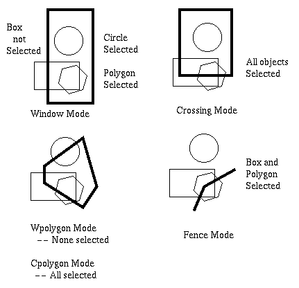
In order to manipulate one or more objects with an editing command, the object or group of objects must first be selected. The selection process is accomplished by drawing a selection figure with the pointing device, then clicking to lock in the selection. The following are useful selection figures, also called selection modes, several of which are illustrated in Figure 4.1:
Point -- One picks a point on the object with the box at the center of the crosshair cursor, then clicks. The selected object's boundary (outline) becomes dotted instead of a solid line.
Window -- This mode is used to select a group of objects. When the pointing device is clicked for the first time, a corner of a selection window or box appears. By dragging the cursor, one establishes the window perimeter. The window mode selects only those objects that are entirely contained within the window, as shown in Figure 4.1.
Crossing -- Similar to the Window mode, this figure is also a box or rectangle, shown in Figure 4.1 by a bold outline. However, all objects that are partially or entirely within the box will be selected. This includes objects that the box or window just touches.
WPolygon -- Using the pointing device in line-drawing mode, one draws a polygon (similar to the LINE command with the CONTIN option). The objects that are entirely contained within the polygon are selected at the next click. Objects not entirely contained in the polygon are not selected.
CPolygon -- This mode is similar to crossing and WPolygon, in the sense that a polygon is draw, and all objects partially or entirely contained within the polygon are selected.
Fence -- Similar to CPolygon mode, a line consisting of a sequence of line segments is drawn. All objects touched by the line are selected when the pointing device is clicked.
All -- Every object in the current drawing is selected.
Last -- The most recently created object is selected. A synonym for this option is Previous.

Figure 4.1. Examples of AutoCAD selection modes.
4.1.2. Object Editing.
The major AutoCAD editing commands require that objects to be first selected by one of the methods described above. Salient editing commands are:
Erase -- Removes selected objects from drawing. One enters the ERASE command or selects the ERASE icon (looks like a pencil eraser), then selects objects, then depresses the carriage return (
Enterkey). The selected object(s) will disappear from the screen but can be recalled immediate after the Erase command by entering the OOPS command on the Command Line.
Move -- Used when one needs to move an object or group of objects from one location to a different location on the current drawing. The MOVE command has the following procedure:
- Select the objects to be relocated using one of the modes listed above.
- Select the base point (a reference point on an object) using the pointing device.
- Select the displacement (amount the base point is to be moved) using the pointing device.
Copy -- Similar to Move, but reproduces objects. This is a useful command that saves much effort in repetitive drawing tasks. The usage of Copy is exactly like that of Move, except that the original object is preserved.
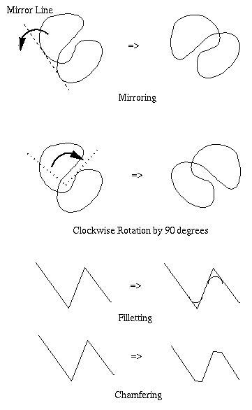
Mirror -- Allows an object to be reflected about a mirror line, where preservation of the original object can be selected by the user. The following procedure pertains:
- Select the objects to be reflected.
- Draw a mirror line (one line segment), as shown in Figure 4.2.
- Select the base point (a reference point on an object) using the pointing device.
- Select the displacement (amount the base point is to be moved) using the pointing device, and the object will be mirrored about the mirror line.
- In answer to a prompt on the Command Line, specify whether or not the original object is to be preserved.
Trim -- This command is similar to a paper cutter or scissors, whereby a part of an object or group of objects may be deleted. One merely draws a trim line (similar to a mirror line) and clicks. The portion of the selected object(s) on the side of the trim line occupied by the pointing device cursor will be deleted.
Extend -- With this command, one selects a boundary edge of an object, then moves the pointing device to the point to which the edge is to be extended. The selected object is reshaped so that the boundary edge now meets the destination point.
Fillet -- Rounds the angles of an object that are less than 180 degrees in subtense. This command is often used to depict a welded joint between two pieces of metal.
Chamfer -- Truncates the vertices of angles in a graphic object (e.g., a polygon) that are less than 180 degrees in subtense. The chamfer depth, which determines how much of the angle will be truncated, is specified in a command option.
Rotate -- With this command, one can rotate objects around a point to change their orientation. One merely selects the objects to be rotated, clicks on a base point (the center of rotation), then moves the pointing device to rotate the object about the base point. Alternatively, the rotation angle can be specfied in response to a prompt that appears on the Command Line.

Figure 4.2. Examples of selected AutoCAD editing commands.
This concludes our overview of basic object selection and editing commands.
4.2. Polylines and Polyline Editing.
It is often useful to draw an object in terms of a connected sequence of line segments. In the preceding section, we saw how the CONTIN option of the LINE command would allow one to draw such a sequence. The concept of polylines takes the idea of connected line segments a step further, by allowing the sequence of segments to be manipulated as a single object.
4.2.1. Drawing Polylines.
The PLINE command is used to draw polylines, and has the following features:
- Usage:
- Step 1. Pick a from-point (origin of the polyline).
Step 2. A list of options is displayed, and one can enter endpoints of the polyline segments.
- Salient Options:
To change linewidth, enter the decimal width, e.g., 0.125 = 1/8". Depending on how you set precision in the UNITS command, AutoCAD may round this number.
Both a starting and an ending width must be specified. AutoCAD defaults the ending width to the starting width. If the widths are different, then tapered lines will be drawn. The i-th line segment in the polyline sequence must have as its starting width the ending width of the (i-1)-th segment.
- WIDTH-- the default width is zero, which means that polylines look like regular lines.
-- the linewidth is specified in terms of a centerline that runs down the middle of the current line segment. To determine the linewidth, multiply the halfwidth by two.- HALFWIDTH
-- the current line segment is drawn to a specific length and is parallel to the last polyline segment drawn. To make the segments connected (not parallel), enter a negative length in response to the prompt.- LENGTH