|
Pattern Name: PipelineProcessing |
AlgorithmStructure Design Space |
This pattern is used for algorithms in which data flows through a sequence of tasks or stages. It represents a "pipelined" form of concurrency, as used for example in a pipelined processor.
The basic idea of this pattern is much like the idea of an assembly line: To perform a sequence of essentially identical calculations, each of which can be broken down into the same sequence of steps, we set up a "pipeline", one stage for each step, with all stages potentially executing concurrently. Each of the sequence of calculations is performed by having the first stage of the pipeline perform the first step, and then the second stage the second step, and so on. As each stage completes a step of a calculation, it passes the calculation-in-progress to the next stage and begins work on the next calculation.
This may be easiest to understand by thinking in terms of the assembly-line analogy: For example, suppose the goal is to manufacture a number of cars, where the manufacture of each car can be separated into a sequence of smaller operations (e.g., installing a windshield). Then we can set up an assembly line (pipeline), with each operation assigned to a different worker. As the car-to-be moves down the assembly line, it is built up by performing the sequence of operations; each worker, however, performs the same operation over and over on a succession of cars.
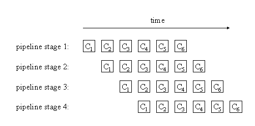
Returning to a more abstract view, if we call the calculations to be performed C1, C2, and so forth, then we can describe operation of a PipelineProcessing program thus: Initially, the first stage of the pipeline is performing the first operation of C1. When that completes, the second stage of the pipeline performs the second operation on C1; simultaneously, the first stage of the pipeline performs the first stage of C2. When both complete, the third stage of the pipeline performs the third operation on C1, the second stage performs the second operation on C2, and the first stage performs the first operation on C3. The following figure illustrates how this works for a pipeline consisting of four stages.

Observe that each stage of the pipeline is inactive during some part of the program: The later stages are inactive early in the program (when C1 has not moved very far "down the pipeline"), and the earlier stages similarly become inactive late in the program (when the last calculation is moving down the pipeline). This pattern therefore is most effective when the number of calculations is large compared to the number of operations/stages required for each one.
Observe also that either the stages of the pipeline must be kept synchronized or there must be some way of buffering work between successive stages. The pattern therefore usually works better if the operations performed by the various stages of the pipeline are all about equally computationally intensive.
The key restriction in this pattern is that it must be possible to overlap the computations, as shown in the preceding figure; e.g., once pipeline stage 1 has finished its part of the calculation for C1, it can proceed to its part of the calculation for C2 while pipeline stage 2 performs its part of the calculation for C1.
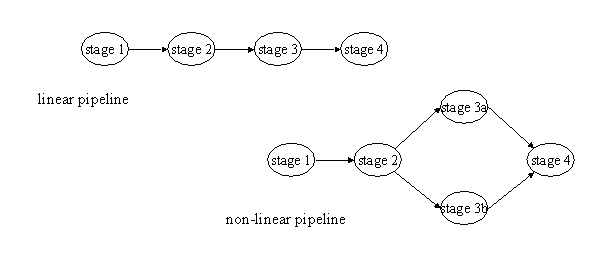
This idea can be extended to include situations in which some operations can be performed concurrently. The figure below illustrates two pipelines, each with four stages. In the second pipeline, the third stage consists of two operations that can be performed concurrently.

These figures suggest that we can represent a pipeline as a directed graph, with vertices corresponding to elements of the calculation and edges indicating dataflow. To preserve the idea of the pipeline, it is necessary that this graph be acyclic, and it is probably best if it does not depart too much from a basically linear structure, in which the elements can be divided into stages, with each stage communicating only with the previous and next stages.
We can describe the linear case more formally, as follows: This pattern describes computations whose goal is to take a sequence of inputs in1, in2, etc. and compute a sequence of outputs out1, out2, etc., where the following is true:
To restate this less formally: For different stages m and n of the pipeline, and different elements Ci and Cj of the sequence of calculations to be performed, stage m of the calculation for Ci can be done independently of stage n of the calculation for Cj. This is what makes the concurrency possible.
Viewing the pattern in terms of tasks, we define one task for each element of the pipeline (one element per stage in a linear pipeline, possibly more for a nonlinear pipeline). Each task can be thought of as having a predecessor (in the previous stage) and a successor (in the next stage), with obvious exceptions for tasks corresponding to the first and last stages of the pipeline and a straightforward generalization to nonlinear pipelines (where a task can have multiple predecessors or successors). Data dependencies are defined as follows. Each task requires as input a sequence of input items from its predecessor (or synchronized sequences from its predecessors); for each input item it generates an output item to be used by its successor (or synchronized groups of items, each group to be distributed among its successors).
Use the PipelineProcessing pattern when:
The pattern is particularly effective when:
Implementations of this pattern include the following key elements:
This pattern is typically used to provide high-level structure for an application; that is, the application is typically structured as an instance of this pattern. This pattern can be particularly effective as the top level of a hierarchical design, with each stage of the pipeline represented by a group of tasks (internally organized using another of the AlgorithmStructure patterns).
What is needed here is a program structure to hold the computations associated with each stage. There are many ways to do this. A particularly effective approach is an SPMD program in which the ID associated with the unit of execution (UE) selects options in a case statement, with each case corresponding to a stage of the pipeline.
What is needed here is a mechanism that provides for the orderly flow of data between stages in the pipeline. This is relatively straightforward to accomplish in a message-passing environment by assigning one process to each function and implementing each function-to-function connection (between successive stages of the pipeline) via a sequence of messages between the corresponding tasks. Since the stages are hardly ever perfectly synchronized, and the amount of work carried out at different stages almost always varies, this flow of data between pipeline stages must usually be both buffered and ordered. Most message-passing environment (e.g., MPI) make this easy to do.
If a message-passing programming environment is not a good fit with the target platform, the programmer will need to explicitly connect the stages in the pipeline with a buffered channel. Such a buffered channel can implemented as a shared queue (using the SharedQueue pattern).
What is needed here is a way of scheduling the tasks that make up the design. Usually all tasks are scheduled to execute concurrently (e.g., as elements of an SPMD program), since this avoids bottlenecks and potential deadlock.
(To be added later.)
Examples of the use of this pattern can be found in image-processing applications.
The CMU task-parallel Fortran test suite ( see the Fx home page) includes examples of this pattern.
Additional examples can be found in [JaJa92].
This pattern is similar to the AsynchronousComposition pattern in that both patterns apply to problems where it is natural to decompose the computation into a collection of semi-independent entities. The difference is that in the PipelineProcessing pattern, these entities interact in a more regular way, with all "stages" of the pipeline proceeding in a loosely synchronous way, whereas in the AsynchronousComposition pattern, there is no such requirement, and the entities can interact in very irregular and asynchronous ways.